
(866)482-7930
www.chargetek.com
1860 Eastman Ave. #107
Ventura, CA 93003
Legacy AC Input Lead-Based Charger Line

CT and CK 150 Series:
Low amperage waterproof
Industrial Battery Chargers

CT 500 Series:
Low amperage waterproof
Industrial Battery Chargers

RTIC-WP Series:
Waterproof High Power
Industrial Battery Chargers

TPRO Series:
Multi-Bank Waterproof
Industrial Battery Chargers

K - Series (LSE)
50 W Charger
Family

F - Series (LPC)
85W Charger
Family

R - Series (LME)
200W Charger
Family

V - Series (MME)
400W Charger
Family

D - Series (MCF)
800W Charger
Family

M - Series (SFE)
1000W Charger
Family
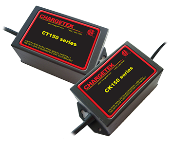
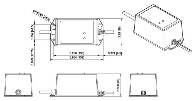
CK150 and CT150
Low amperage two and three stage chargers
- Safety Agency Certification
- Reverse polarity protection
- Over voltage and current protection
- Rugged and waterproof
- Fully encapsulated and hermetically sealed
INPUT: 110VAC
INPUT: 220VAC
Two Stage
Chargers
Three Stage
Chargers
Two Stage
Chargers
Three Stage
Chargers
Input transient protection
Reverse Polarity Protection
Fully Encapsulated
and Hermetically Sealed

Low Standby
Current

Three Stage
Charging
*
Mode Indicators

Ignition Protection
Over Voltage and Current Protection
Easily Installed
Input Transient Protection.
Input power transient protection prevents damage to the charger in the event of high voltage transients. These events are usually caused by inclement weather or heavy machinery on the same power line. The duration of the transient typically exists for tens of microseconds and generate thousands of joules of energy.
Reverse polarity protection
Internal reverse polarity protection circuitry prevents dangerous current flow when the battery is connected in the reverse direction. No external or internal fuses should blow when this occurs since the reverse current is in the milliamp range.
Fully encapsulated and hermetically sealed
The product is fully encapsulated with UL approved thermally conductive and flame retardant 94-V0 material. The encapsulation protects the product from contaminants such as water, dust and humidity. It also provides inherent vibration resistance since the internal components are incapable of movement.
Low standby current
The standby current is very low (see spec sheets for more details). This drain is substantially lower on newer units although still suitable and most applications since the drain only occurs during AC power failure.
Three Stage Charging
The charging algorithm is an optimal three state charging technique which is depicted in the graph below. Please refer to this link for more detailed information. The charger can be left connected to the battery indefinitely and will not overcharge. (CT models use two stage charging).
Mode Indicators
Two LED mode indicators provide state of charge and fault information.
Ignition Protection
Ignition protection is provided through the full encapsulation of the charger.
Over voltage and current protection
Overvoltage protection prevents excessive voltage to the battery in the event of the primary regulation loop failure or other adverse conditions. Overcurrent protection prevents excessive current in the event of a short-circuit or battery overload. Once the fault is removed normal operation is resumed.
Easily Installed
The charger can be used as a portable unit or permanently mounted on board. Encapsulation prevents internal components from shaking loose during vibration and movement. External mounting strap should be added or extreme vibration conditions.
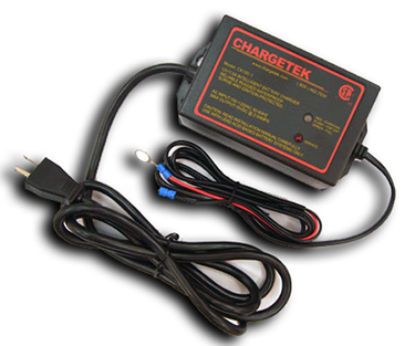
CT500
Single and dual bank waterproof chargers
- Three stage lead based charger
- Safety Agency Certification
- Mode indicators
- Low standby current
- Reverse polarity protection
110VAC INPUT MODELS
220VAC INPUT MODELS

Input transient protection
Reverse Polarity Protection
Fully Encapsulated
and Hermetically Sealed

Low Standby
Current

Three State
Charging
Mode Indicators

Ignition Portection
Over Voltage and Current Protection
Easily Installed
Input Transient Protection.
Input power transient protection prevents damage to the charger in the event of high voltage transients. These events are usually caused by inclement weather or heavy machinery on the same power line. The duration of the transient typically exists for tens of microseconds and generate thousands of joules of energy.
Reverse polarity protection
Internal reverse polarity protection circuitry prevents dangerous current flow when the battery is connected in the reverse direction. No external or internal fuses should blow when this occurs since the reverse current is in the milliamp range.
Fully encapsulated and hermetically sealed
The product is fully encapsulated with UL approved thermally conductive and flame retardant 94-V0 material. The encapsulation protects the product from contaminants such as water, dust and humidity. It also provides inherent vibration resistance since the internal components are incapable of movement.
Low standby current
The standby current is very low (see spec sheets for more details). This drain is substantially lower on newer units although still suitable and most applications since the drain only occurs during AC power failure.
Three State Charging
The charging algorithm is an optimal three state charging technique which is depicted in the graph below. Please refer to this link for more detailed information. The charger can be left connected to the battery indefinitely and will not overcharge.
Mode Indicators
Two LED mode indicators provide state of charge and fault information.
Ignition Protection
Ignition protection is provided through the full encapsulation of the charger.
Over voltage and current protection
Overvoltage protection prevents excessive voltage to the battery in the event of the primary regulation loop failure or other adverse conditions. Overcurrent protection prevents excessive current in the event of a short-circuit or battery overload. Once the fault is removed normal operation is resumed.
Easily Installed
The charger can be used as a portable unit or permanently mounted on board. Encapsulation prevents internal components from shaking loose during vibration and movement. External mounting strap should be added or extreme vibration conditions.
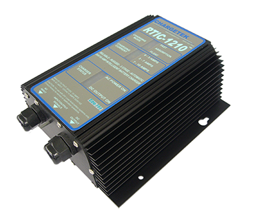
RTIC
Single bank high power chargers
- Three stage lead based charger
- Safety Agency Certification
- Mode indicators
- Low standby current
- Reverse polarity protection
110VAC INPUT MODELS
220VAC INPUT MODELS
Input transient protection
Reverse Polarity Protection
Fully Encapsulated
and Hermetically Sealed

Low Standby
Current

Three State
Charging
Mode Indicators

Ignition Portection
Over Voltage and Current Protection
Easily Installed
Input Transient Protection.
Input power transient protection prevents damage to the charger in the event of high voltage transients. These events are usually caused by inclement weather or heavy machinery on the same power line. The duration of the transient typically exists for tens of microseconds and generate thousands of joules of energy.
Reverse polarity protection
Internal reverse polarity protection circuitry prevents dangerous current flow when the battery is connected in the reverse direction. No external or internal fuses should blow when this occurs since the reverse current is in the milliamp range.
Fully encapsulated and hermetically sealed
The product is fully encapsulated with UL approved thermally conductive and flame retardant 94-V0 material. The encapsulation protects the product from contaminants such as water, dust and humidity. It also provides inherent vibration resistance since the internal components are incapable of movement.
Low standby current
The standby current is very low (see spec sheets for more details). This drain is substantially lower on newer units although still suitable and most applications since the drain only occurs during AC power failure.
Three State Charging
The charging algorithm is an optimal three state charging technique which is depicted in the graph below. Please refer to this link for more detailed information. The charger can be left connected to the battery indefinitely and will not overcharge.
Mode Indicators
Two LED mode indicators provide state of charge and fault information.
Ignition Protection
Ignition protection is provided through the full encapsulation of the charger.
Over voltage and current protection
Overvoltage protection prevents excessive voltage to the battery in the event of the primary regulation loop failure or other adverse conditions. Overcurrent protection prevents excessive current in the event of a short-circuit or battery overload. Once the fault is removed normal operation is resumed.
Easily Installed
The charger can be used as a portable unit or permanently mounted on board. Encapsulation prevents internal components from shaking loose during vibration and movement. External mounting strap should be added or extreme vibration conditions.
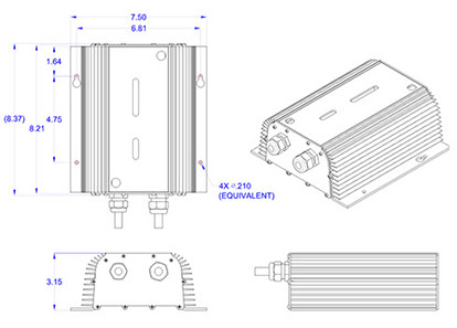
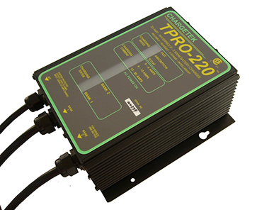
TPRO
Multi-bank waterproof chargers
- Three stage lead based charger
- Safety Agency Certification
- Mode indicators
- Low standby current
- Reverse polarity protection
110VAC INPUT MODELS
Two Bank
Three Bank
220VAC INPUT MODELS
Two Bank
Three Bank
Input transient protection
Reverse Polarity Protection
Fully Encapsulated
and Hermetically Sealed

Low Standby
Current

Three State
Charging
Mode Indicators

Ignition Portection
Over Voltage and Current Protection
Easily Installed
Input Transient Protection.
Input power transient protection prevents damage to the charger in the event of high voltage transients. These events are usually caused by inclement weather or heavy machinery on the same power line. The duration of the transient typically exists for tens of microseconds and generate thousands of joules of energy.
Reverse polarity protection
Internal reverse polarity protection circuitry prevents dangerous current flow when the battery is connected in the reverse direction. No external or internal fuses should blow when this occurs since the reverse current is in the milliamp range.
Fully encapsulated and hermetically sealed
The product is fully encapsulated with UL approved thermally conductive and flame retardant 94-V0 material. The encapsulation protects the product from contaminants such as water, dust and humidity. It also provides inherent vibration resistance since the internal components are incapable of movement.
Low standby current
The standby current is very low (see spec sheets for more details). This drain is substantially lower on newer units although still suitable and most applications since the drain only occurs during AC power failure.
Three State Charging
The charging algorithm is an optimal three state charging technique which is depicted in the graph below. Please refer to this link for more detailed information. The charger can be left connected to the battery indefinitely and will not overcharge.
Mode Indicators
Two LED mode indicators provide state of charge and fault information.
Ignition Protection
Ignition protection is provided through the full encapsulation of the charger.
Over voltage and current protection
Overvoltage protection prevents excessive voltage to the battery in the event of the primary regulation loop failure or other adverse conditions. Overcurrent protection prevents excessive current in the event of a short-circuit or battery overload. Once the fault is removed normal operation is resumed.
Easily Installed
The charger can be used as a portable unit or permanently mounted on board. Encapsulation prevents internal components from shaking loose during vibration and movement. External mounting strap should be added or extreme vibration conditions.
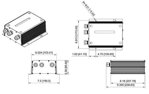
LSE
K-Series
Chargers
LSE Highlights
Power Level: up to 50 W
Cooling: Convection
Size: 6.2"L x 2.4"W x 1.6"H
Comm Options: None
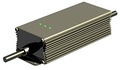
The LSE series is designed to satisfy stringent mechanical and environmental requirements. This enclosure is hermetically sealed, impervious to pollutants and contaminants, easily installed and suitable for power requirements up to 50 watts. Higher power levels and higher battery voltages can be obtained depending upon the particular input/output voltage ratios. Please inquire if the required charging voltage is not in the table. The LSE is factory programmable to accommodate several user defined charging algorithms. Many nonstandard features can be accommodated with an extended enclosure length Customization is offered to include options such has temperature compensation, controls and monitoring signals and wireless capability.
AC Input Chargers
DC Input Chargers
Useful
Links
Outline, Mounting and Benefits

Input transient protection
Reverse Polarity Protection
Fully Encapsulated
and Hermetically Sealed

Low Standby
Current
Charging and Protection
Mode Indicators
Safety Agency Certification
Easily Installed

Communications

Extended Temp. Range
Input Transient Protection.
Input power transient protection prevents damage to the charger in the event of high voltage transients. These events are usually caused by inclement weather or heavy machinery on the same power line. The duration of the transient typically exists for tens of microseconds and generate thousands of joules of energy.
Reverse polarity protection
Internal reverse polarity protection circuitry prevents dangerous current flow when the battery is connected in the reverse direction. No external or internal fuses should blow when this occurs since the reverse current is in the milliamp range.
Fully encapsulated and hermetically sealed
The product is fully encapsulated with UL approved thermally conductive and flame retardant 94-V0 material. The encapsulation protects the product from contaminants such as water, dust and humidity. It also provides inherent vibration resistance since the internal components are incapable of movement.
Low standby current
The standby current is very low (see spec sheets for more details). This drain is substantially lower on newer units although still suitable and most applications since the drain only occurs during AC power failure.
Charging and Protection
Standard and custom charge algorithms for many battery chemistries are available. Charging voltage and current is precisely controlled to insure an efficient and reliable recharging process. Over voltage /current/ temperature protection is standard on all models.
Mode Indicators
Standard units have three LEDs indicating various charging and status conditions.`
Safety Agency Certified.
This product is certified to UL/CSA 1236 which is a stringent Marine specification. Please reference this link.....(link)
Easily Installed
The charger can be used as a portable unit or permanently mounted on board. Encapsulation prevents internal components from shaking loose during vibration and movement. External mounting strap should be added or extreme vibration conditions.
Communications
Several communications options are available and are explained in the tools section under control and monitoring.
Extended Temperature Range
An extended temperature range beyond the stated data sheet limits is available upon request.

3D PDF

Outline and Mounting
LPC
F-Series
Chargers
LPC Highlights
Power Level: up to 85 W
Cooling: Convection
Size: 6.0"L x 3.5"W x 2.6"H
Comm Options: None
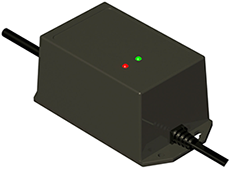
The LPC product line is especially suited for high end industrial applications and severe environments. This product series is versatile, rugged, hermetically sealed, fully encapsulated and waterproof. The LPC series is designed to satisfy stringent mechanical and environmental requirements. This product family is suitable for power requirements up to 85 watts and higher power levels and battery voltages can be obtained depending upon the particular input/output voltage ratios. Please inquire if the required charging voltage is not in the table. The LPC series is factory programmable to accommodate several user defined charging algorithms. Many nonstandard features can be accommodated with an extended enclosure length. Customization is offered to include options such has temperature compensation, controls and monitoring signals and wireless capability.
AC Input Chargers
DC Input Chargers
Useful
Links
Outline, Mounting and Benefits

Input transient protection
Reverse Polarity Protection
Fully Encapsulated
and Hermetically Sealed

Low Standby
Current
Charging and Protection
Mode Indicators

Safety Agency Certification
Easily Installed

Communications

Extended Temp. Range
Input Transient Protection.
Input power transient protection prevents damage to the charger in the event of high voltage transients. These events are usually caused by inclement weather or heavy machinery on the same power line. The duration of the transient typically exists for tens of microseconds and generate thousands of joules of energy.
Reverse polarity protection
Internal reverse polarity protection circuitry prevents dangerous current flow when the battery is connected in the reverse direction. No external or internal fuses should blow when this occurs since the reverse current is in the milliamp range.
Fully encapsulated and hermetically sealed
The product is fully encapsulated with UL approved thermally conductive and flame retardant 94-V0 material. The encapsulation protects the product from contaminants such as water, dust and humidity. It also provides inherent vibration resistance since the internal components are incapable of movement.
Low standby current
The standby current is very low (see spec sheets for more details). This drain is substantially lower on newer units although still suitable and most applications since the drain only occurs during AC power failure.
Charging and Protection
Standard and custom charge algorithms for many battery chemistries are available. Charging voltage and current is precisely controlled to insure an efficient and reliable recharging process. Over voltage /current/ temperature protection is standard on all models.
Mode Indicators
Standard units have three LEDs indicating various charging and status conditions.
Safety Agency Certified.
This product is certified to UL/CSA 1236 which is a stringent Marine specification. Please reference this link.....(link)
Easily Installed
The charger can be used as a portable unit or permanently mounted on board. Encapsulation prevents internal components from shaking loose during vibration and movement. External mounting strap should be added or extreme vibration conditions.
Communications
Several communications options are available and are explained in the tools section under control and monitoring.
Extended Temperature Range
An extended temperature range beyond the stated data sheet limits is available upon request.

3D PDF

Outline and Mounting
LME
R-Series
Chargers
LME Highlights
Power Level: up to 200 W
Cooling: Convection
Size: 6.0"L x 4.4"W x 2.0"H
Comm Options: Discrete I/O
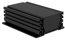
The LME product line satisfies power requirements up to 300 watts using only convection cooling, depending upon the input and output definitions. It can be programmed for all battery types and is hermetically sealed making it impervious to pollutants and contaminants. The LME is available in a standard 11 - 20VDC input and we offer an extended input/output range up to 450VDC. Wireless capability and discrete signals can be added upon request.
AC Input Chargers
DC Input Chargers
Useful
Links
Outline, Mounting and Benefits

Input transient protection
Reverse Polarity Protection
Fully Encapsulated
and Hermetically Sealed

Low Standby
Current
Charging and Protection
Mode Indicators
Safety Agency Certification
Easily Installed

Communications

Extended Temp. Range
Input Transient Protection.
Input power transient protection prevents damage to the charger in the event of high voltage transients. These events are usually caused by inclement weather or heavy machinery on the same power line. The duration of the transient typically exists for tens of microseconds and generate thousands of joules of energy.
Reverse polarity protection
Internal reverse polarity protection circuitry prevents dangerous current flow when the battery is connected in the reverse direction. No external or internal fuses should blow when this occurs since the reverse current is in the milliamp range.
Fully encapsulated and hermetically sealed
The product is fully encapsulated with UL approved thermally conductive and flame retardant 94-V0 material. The encapsulation protects the product from contaminants such as water, dust and humidity. It also provides inherent vibration resistance since the internal components are incapable of movement.
Low standby current
The standby current is very low (see spec sheets for more details). This drain is substantially lower on newer units although still suitable and most applications since the drain only occurs during AC power failure.
Charging and Protection
Standard and custom charge algorithms for many battery chemistries are available. Charging voltage and current is precisely controlled to insure an efficient and reliable recharging process. Over voltage /current/ temperature protection is standard on all models.
Mode Indicators
Standard units have three LEDs indicating various charging and status conditions.
Safety Agency Certified.
This product is certified to UL/CSA 1236 which is a stringent Marine specification. Please reference this link.....(link)
Easily Installed
The charger can be used as a portable unit or permanently mounted on board. Encapsulation prevents internal components from shaking loose during vibration and movement. External mounting strap should be added or extreme vibration conditions.
Communications
Several communications options are available and are explained in the tools section under control and monitoring.
Extended Temperature Range
An extended temperature range beyond the stated data sheet limits is available upon request.

3D PDF

Outline and Mounting
MME
V-Series
Chargers
MME Highlights
Power Level: up to 400 W
Cooling: Convection
Size: 11.2"L x 6.0"W x 3.9"H
Comm Options: Discrete I/O
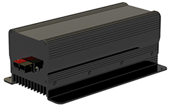
The MME series is designed to satisfy stringent mechanical and environmental requirements. This enclosure is hermetically sealed, partially encapsulated in critical areas, impervious to pollutants and contaminants. The standard product has an 400 watt capability but higher power levels and battery voltages can be obtained depending upon the particular input/output voltage ratios. Please inquire if the required charging voltage is not in the table. The MME is factory programmable to accommodate several user defined charging algorithms. Many nonstandard features can be accommodated with an extended enclosure length. Customization is offered to include options such has temperature compensation, controls and monitoring signals and wireless capability.
AC Input Chargers
DC Input Chargers
Useful
Links
Outline, Mounting and Benefits

I`nput transient protection
Reverse Polarity Protection
Fully Encapsulated
and Hermetically Sealed

Low Standby
Current
Charging and Protection
Mode Indicators
Safety Agency Certification
Easily Installed

Communications

Extended Temp. Range
Input Transient Protection.
Input power transient protection prevents damage to the charger in the event of high voltage transients. These events are usually caused by inclement weather or heavy machinery on the same power line. The duration of the transient typically exists for tens of microseconds and generate thousands of joules of energy.
Reverse polarity protection
Internal reverse polarity protection circuitry prevents dangerous current flow when the battery is connected in the reverse direction. No external or internal fuses should blow when this occurs since the reverse current is in the milliamp range.
Fully encapsulated and hermetically sealed
The product is fully encapsulated with UL approved thermally conductive and flame retardant 94-V0 material. The encapsulation protects the product from contaminants such as water, dust and humidity. It also provides inherent vibration resistance since the internal components are incapable of movement.
Low standby current
The standby current is very low (see spec sheets for more details). This drain is substantially lower on newer units although still suitable and most applications since the drain only occurs during AC power failure.
Charging and Protection
Standard and custom charge algorithms for many battery chemistries are available. Charging voltage and current is precisely controlled to insure an efficient and reliable recharging process. Over voltage /current/ temperature protection is standard on all models.
Mode Indicators
Standard units have three LEDs indicating various charging and status conditions.
Safety Agency Certified.
This product is certified to UL/CSA 1236 which is a stringent Marine specification. Please reference this link.....(link)
Easily Installed
The charger can be used as a portable unit or permanently mounted on board. Encapsulation prevents internal components from shaking loose during vibration and movement. External mounting strap should be added or extreme vibration conditions.
Communications
Several communications options are available and are explained in the tools section under control and monitoring.
Extended Temperature Range
An extended temperature range beyond the stated data sheet limits is available upon request.

3D PDF

Outline and Mounting
MCF
D-Series
Chargers
MCF Highlights
Power Level: up to 800 W
Cooling: Forced Air
Size: 9.3"L x 5.0"W x 2.2"H
Comm Options: All
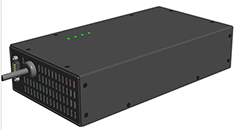
The MCF series is a fan-cooled product line designed primarily for indoor applications. The enclosure is not sealed, however, the circuit boards are conformally coated to provide resistance to pollutants and contaminants. When the charger is in float or low power modes and substantial cooling is not required, fan speed is controlled to eliminate or attenuate audible noise. The MCF series is suitable for power requirements up to 800 watts. Higher power levels and battery voltages can be obtained depending upon the particular input/output voltage ratios. Please inquire if the required charging voltage is not in the table, which lists only the more common configurations. The MCF is factory programmable to accommodate several user defined charging algorithms. Customization is offered to include options such has temperature compensation, controls/monitoring signals, digital communication and wireless capability. Please visit this link to review the options available.`
AC Input Chargers
DC Input Chargers
Useful
Links
Outline, Mounting and Benefits

Input transient protection
Reverse Polarity Protection
Fully Encapsulated
and Hermetically Sealed

Low Standby
Current
Charging and Protection
Mode Indicators

Safety Agency Certification
Easily Installed

Communications

Extended Temp. Range
Input Transient Protection.
Input power transient protection prevents damage to the charger in the event of high voltage transients. These events are usually caused by inclement weather or heavy machinery on the same power line. The duration of the transient typically exists for tens of microseconds and generate thousands of joules of energy.
Reverse polarity protection
Internal reverse polarity protection circuitry prevents dangerous current flow when the battery is connected in the reverse direction. No external or internal fuses should blow when this occurs since the reverse current is in the milliamp range.
Fully encapsulated and hermetically sealed
The product is fully encapsulated with UL approved thermally conductive and flame retardant 94-V0 material. The encapsulation protects the product from contaminants such as water, dust and humidity. It also provides inherent vibration resistance since the internal components are incapable of movement.
Low standby current
The standby current is very low (see spec sheets for more details). This drain is substantially lower on newer units although still suitable and most applications since the drain only occurs during AC power failure.
Charging and Protection
Standard and custom charge algorithms for many battery chemistries are available. Charging voltage and current is precisely controlled to insure an efficient and reliable recharging process. Over voltage /current/ temperature protection is standard on all models.
Mode Indicators
Standard units have three LEDs indicating various charging and status conditions.
Safety Agency Certified.
This product is certified to UL/CSA 1236 which is a stringent Marine specification. Please reference this link.....(link)
Easily Installed
The charger can be used as a portable unit or permanently mounted on board. Encapsulation prevents internal components from shaking loose during vibration and movement. External mounting strap should be added or extreme vibration conditions.
Communications
Several communications options are available and are explained in the tools section under control and monitoring.
Extended Temperature Range
An extended temperature range beyond the stated data sheet limits is available upon request.

3D PDF
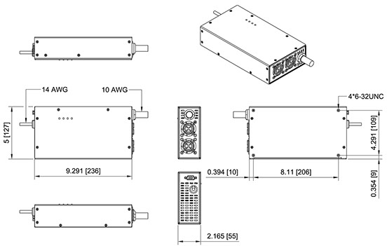
Outline and Mounting
SFE
M-Series
Chargers
SFE Highlights
Power Level: up to 1000 W
Cooling: Forced Air
Size: 6.5"L x 5.7"W x 2.8"H
Comm Options: All
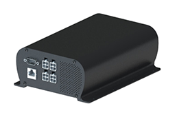
The SFE series is a hybrid fan-cooled and sealed unit. This patent pending product line is designed primarily for demanding environments with high power density requirements. The critical components are encapsulated and the entire enclosure is hermetically sealed. All circuit boards are conformally coated to provide resistance to pollutants and contaminants. When the charger is in float or low power modes and substantial cooling is not required, fan speed is controlled to eliminate or attenuate audible noise. The fans are easily field replaceable and does not require opening up the sealed areas. The SFE series is suitable for power requirements up to 1000 watts. Higher power levels and battery voltages can be obtained depending upon the particular input/output voltage ratios. Please inquire if the required charging voltage is not in the table. The SFE line is factory programmable to accommodate several user defined charging algorithms. Customization is offered to include options such has temperature compensation, controls/monitoring signals, digital communication and wireless capability. Please visit this link to review the options available.
AC Input Chargers
DC Input Chargers
Useful
Links
Outline, Mounting and Benefits

Input transient protection
Reverse Polarity Protection
Fully Encapsulated
and Hermetically Sealed

Low Standby
Current
Charging and Protection
Mode Indicators
Safety Agency Certification
Easily Installed

Communications

Extended Temp. Range
Input Transient Protection.
Input power transient protection prevents damage to the charger in the event of high voltage transients. These events are usually caused by inclement weather or heavy machinery on the same power line. The duration of the transient typically exists for tens of microseconds and generate thousands of joules of energy.
Reverse polarity protection
Internal reverse polarity protection circuitry prevents dangerous current flow when the battery is connected in the reverse direction. No external or internal fuses should blow when this occurs since the reverse current is in the milliamp range.
Fully encapsulated and hermetically sealed
The product is fully encapsulated with UL approved thermally conductive and flame retardant 94-V0 material. The encapsulation protects the product from contaminants such as water, dust and humidity. It also provides inherent vibration resistance since the internal components are incapable of movement.
Low standby current
The standby current is very low (see spec sheets for more details). This drain is substantially lower on newer units although still suitable and most applications since the drain only occurs during AC power failure.
Charging and Protection
Standard and custom charge algorithms for many battery chemistries are available. Charging voltage and current is precisely controlled to insure an efficient and reliable recharging process. Over voltage /current/ temperature protection is standard on all models.
Mode Indicators
Standard units have three LEDs indicating various charging and status conditions.
Safety Agency Certified.
This product is certified to UL/CSA 1236 which is a stringent Marine specification. Please reference this link.....(link)
Easily Installed
The charger can be used as a portable unit or permanently mounted on board. Encapsulation prevents internal components from shaking loose during vibration and movement. External mounting strap should be added or extreme vibration conditions.
Communications
Several communications options are available and are explained in the tools section under control and monitoring.
Extended Temperature Range
An extended temperature range beyond the stated data sheet limits is available upon request.

3D PDF
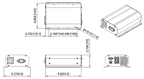
Outline and Mounting
AC or DC Input Multi-Chemistry Charger Line

Multibank Chargers:
Low amperage charger banks, many options

Power Systems:
Power modules, backup battery/chargers, etc.

PRODUCTS


© 2022 Chargetek, Inc.
1860 Eastman Ave. #107
Ventura, CA 93003
p: (866)482-7930 • f: (805)650-7936
email: sales@chargetek.com
Product Overview


