
(866)482-7930
www.chargetek.com
1860 Eastman Ave. #107
Ventura, CA 93003
POWER SYSTEMS
BATTERY
BACK UP
BATTERY
BATTERY
CHARGER
EMI
FILTER
TRANSIENT
PROTECTION
PFC (AC)
BOOST (DC)
POWER
MODULE N
POWER
MODULE 1
OVERVIEW
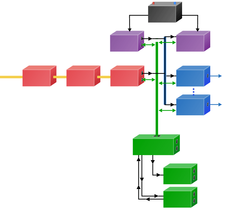
BATTERY BACK UP UNIT
The BBU converts the battery voltage to the required magnitude of the DC bus voltage to maintain uninterrupted output power in the event of AC line failure, glitches or sags. It also provides galvanic isolation via a high-frequency transformer which allows the BBU output to be referenced to any ground. The BBU is always operating at a voltage slightly less than the DC bus voltage in order to provide seamless transition between AC power and BBU power during line failures, transients or disturbances.
BATTERY
The battery can be any chemistry that most appropriately fits the application it should be sized to provide 20% more capacity than the maximum amount of power required over a given time period. In the in the text box, specify these parameters and also include the battery chemistry desired.
BATTERY CHARGER
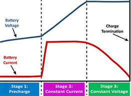
When the AC line power is available, the battery charger replenishes the battery and the battery will remain at full charge until an AC line sag or failure occurs. The battery charger is automatically turned off when AC power fails to preserve battery power. The charts below describe the charge algorithm for the most common battery chemistries below.
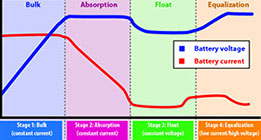
Lead-Based Charge Algorithm
Lithium/LiPO Charge Algorithm
For more information see Charging Basics
EMI FILTER
The EMI filter function is to reduce high frequency electronic emmisions generated by the power electronics that may cause interference with other devices. The emissions either conducted or radiated, conducted EMI is propagated by electrical conductors and radiated EMI propogates through the air. The frequency range for EMI emissions can extend from line frequency up to the gigahertz range.
EMI is generated from the switching of electrical current and comes from a variety of sources including electronic power supplies.
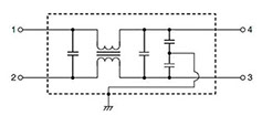 An EMI filter for a power conversion equipment is usually comprised of capacitors and inductors configured in various filter topologies.
The EMI filter has to meet relevant safety standards for leakage current to ground and temperature rise. The capacitors are individually safety certified as two groups: Capacitors C1 and C2 are X capacitors and are across the input terminals. The “Y” capacitors, C3 and C4 are placed from the AC circuit to earth ground.
TRANSIENT SUPPRESSION
Transient surge voltages can be generated from a variety of sources and are a major cause of poor
operational or long term reliability. Surge voltages can also cause erratic behavior in
control circuits and effect the normal operation of
electronics. Transient surge voltages can usually be
attributed to:
• Sudden load changes in other equipment on the same power line
• Power source fluctuations
• Coupled electronic disturbances via cables
• Opening or closing of switch contacts in high power machinery
• Lightning
The power supply and data cables are common entry points for conducted and coupled transient surge voltages.
In many systems, a common power supply is shared by a number of electronic modules.
TVS devices can be categorized as a cable, crowbar, clamping or filter device. Each TVS option has unique advantages and disadvantages depending on the application. Many power systems use a combination of TVS devices to create a protection circuit that combines the advantages of the various TVS options.
AC/DC w/PFC
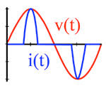
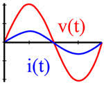
Power Factor Correction is a technique that promotes efficient energy consumption from the power grid. Power Factor correction is employed inside common electrical and electronic equipment that are powered from the AC outlet. Power factor correction enables the equipment to maximize the active power draw and minimize the reactive power draw from the AC outlet. The POWER FACTOR is the ratio between the true or actual power (kW) to the apparent power (kVA) of a device. The ideal power factor is one, which would be the same as a resistor.
The AC input current waveform without power factor correction is shown below:
AC current with PFC appears resistive and is in phase and in proportion to AC voltage
POWER MODULE N
Any number of power supplies can be connected to the DC bus. In each box, define the output power requirements for each power supply as follow:
Vin = Vo = Io =
POWER MODULE 1
Any number of power supplies can be connected to the DC bus. In each box, define the output power requirements for each power supply as follow:
Vin = Vo = Io =
DIGITAL CONTROL AND COMMUNICATIONS
Digital Interface several options are available for the digital interface please see our controls and monitoring section in the tools page for more detail here you can indicate what protocol you would like to have, including RS-232 and RS-485. We can also incorporate SM bus interface for the battery charger. Also, please include a list of bells and whistles that your system requirements have defined and we can program them as required.
POWER SYSTEM OVERVIEW
Chargetek power bricks offer a very versatile and easily configurable power system platform. A complete turnkey customized solution from input to output per customer specifications can be implemented for a wide variety of applications. Alternatively, a power system using the input bricks can be used to generate a regulated DC bus and power an arbitrary source of DC/DC converters, DC/AC inverters and peripherals.
Both AC and DC input power requirements can be satisfied. For AC applications, a power factor correction (PFC) option for both single phase and three-phase systems up to 5KW are available at AC voltages ranging from 85 to 480 VAC. The corresponding regulated DC bus voltage can be designed to optimize performance and efficiency for a given AC input voltage and battery backup requirement.
For DC inputs requirements, an optional boost stage can employed and is very useful and frequently required for low input voltages in the 9 - 15VDC range that commonly encountered in the automotive and transportation industry
Request more information about your requirements
DISCRETE
SIGNALS
USER
DIGITAL
INTERFACE
INPUT
POWER


© 2022 Chargetek, Inc.
1860 Eastman Ave. #107
Ventura, CA 93003
p: (866)482-7930 • f: (805)650-7936
email: sales@chargetek.com
Product Overview


