(866)482-7930
www.chargetek.com
1860 Eastman Ave. #107
Ventura, CA 93003
DC INPUT MULTIBANK CHARGER SYSTEMS
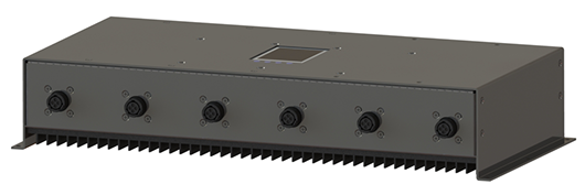
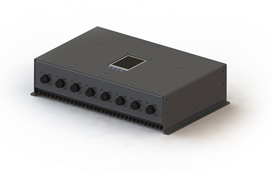
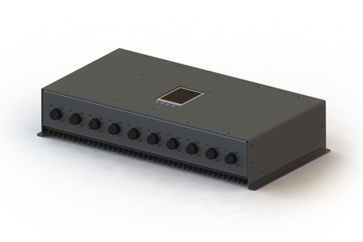
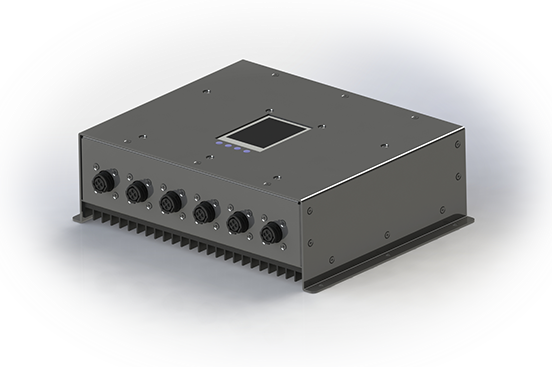
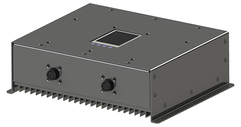
The DC input multibank series is one of the most innovative in the industry. Each bank is fully isolated and independently configurable. The enclosure is sealed from dust, other environmental contaminants. This series can satisfy multibank requirements for shop charging, fleet charging, emergency and maintenance depots, warehouse and restoration applications.
There are six factory standard battery algorithms and can also be customized upon request. A user friendly LCD display is very informative with a digital volt meter, amp meter, charging status and is also used for programming charging options. A communication interface for external monitoring and control via a GUI or computer interface is optional. Field replaceable fan cooled options can be added increased power or elevated temperatures. Batteries may be left connected indefinitely.
Selecting the proper multibank for your application is very simple please follow the steps below:
1. Select the input power option
2. Select the battery chemistry
3. Select the number of battery banks
4. The part number will be automatically generated
5. Downloadable outline & mounting drawings, CAD files and the data sheet link are below
Series
Number Banks
Battery
Chem
Input
Output
Voltage
(or xS)
Output
Current
Options
Part Number
Input Power Options
Battery Chemistry Options
LEAD
LITHIUM
LiPO
12V Battery
24V Battery
G
36V Battery
48V Battery
1S - 3S Battery
4S - 8S Battery
T
9S - 13S Battery
14S - 18S Battery
1S - 3S Battery
4S - 8S Battery
L
9S - 13S Battery
14S - 18S Battery
Number of Banks
6
8
10
2
6 Bank Charger Options (select Enclosure/Voltage)
Enclosure Amps/Bank
Enclosure Amps/Bank
Enclosure Amps/Bank
Enclosure Amps/Bank
6
MA
12
MB
5
MB
3
MA
6
MB
3
MA
4
MB
2
MA
3
MB
2
MA
12
12
MB
12
5
MB
12
3
MA
24
6
MB
24
3
MA
36
4
MB
36
2
MA
48
3
MB
48
2
8 Bank Charger Options (select Enclosure/Voltage)
Enclosure Amps/Bank
Enclosure Amps/Bank
Enclosure Amps/Bank
Enclosure Amps/Bank
8
MA
10
MB
5
MB
3
MA
5
MB
3
MA
3
MB
2
MA
3
MB
2
MA
12
10
MB
12
5
MB
12
3
MA
24
5
MB
24
3
MA
36
3
MB
36
2
MA
48
3
MB
48
2
10 Bank Charger Options (select Enclosure/Voltage)
Enclosure Amps/Bank
Enclosure Amps/Bank
Enclosure Amps/Bank
Enclosure Amps/Bank
10
MA
8
MB
5
MB
3
MA
4
MB
3
MA
3
MB
2
MA
2
MB
2
MA
12
8
MB
12
5
MB
12
3
MA
24
4
MB
24
3
MA
36
3
MB
36
2
MA
48
2
MB
48
2
2 Bank Charger Options (select Enclosure/Voltage)
Enclosure Amps/Bank
Enclosure Amps/Bank
Enclosure Amps/Bank
Enclosure Amps/Bank
MA
40
MB
20
MB
10
MA
20
MB
10
MB
5
MA
12
MB
7
MB
3
MA
10
MB
5
MB
3
MA
12
40
MB
12
20
MB
12
10
MA
24
20
MB
24
10
MB
24
5
MA
36
12
MB
36
7
MB
36
3
MA
48
10
MB
48
5
MB
48
3
2
18-36VDC
30-50VDC
38-75VDC
72-140VDC
08
09
10
11
Enclosures

Input transient protection
Reverse Polarity Protection
Fully Encapsulated
and Hermetically Sealed

Low Standby
Current
Charging and Protection
Mode Indicators
Safety Agency Certification
Easily Installed

Communications

Extended Temp. Range
Input Transient Protection.
Input power transient protection prevents damage to the charger in the event of high voltage transients. These events are usually caused by inclement weather or heavy machinery on the same power line. The duration of the transient typically exists for tens of microseconds and generate thousands of joules of energy.
Reverse polarity protection
Internal reverse polarity protection circuitry prevents dangerous current flow when the battery is connected in the reverse direction. No external or internal fuses should blow when this occurs since the reverse current is in the milliamp range.
Fully encapsulated and hermetically sealed
The product is fully encapsulated with UL approved thermally conductive and flame retardant 94-V0 material. The encapsulation protects the product from contaminants such as water, dust and humidity. It also provides inherent vibration resistance since the internal components are incapable of movement.
Low standby current
The standby current is very low (see spec sheets for more details). This drain is substantially lower on newer units although still suitable and most applications since the drain only occurs during AC power failure.
Charging and Protection
Standard and custom charge algorithms for many battery chemistries are available. Charging voltage and current is precisely controlled to insure an efficient and reliable recharging process. Over voltage /current/ temperature protection is standard on all models.
Mode Indicators
Standard units have three LEDs indicating various charging and status conditions.
Safety Agency Certified.
This product is certified to UL/CSA 1236 which is a stringent Marine specification. Please reference this link.....(link)
Easily Installed
The charger can be used as a portable unit or permanently mounted on board. Encapsulation prevents internal components from shaking loose during vibration and movement. External mounting strap should be added or extreme vibration conditions.
Communications
Several communications options are available and are explained in the tools section under control and monitoring.
Extended Temperature Range
An extended temperature range beyond the stated data sheet limits is available upon request.
6-Bank MA 2D
6-Bank MA 3D
2-Bank MA/MB 2D
8-Bank MA/MB 2D
10-Bank MA/MB 2D
2-Bank MA/MB 3D
8-Bank MA/MB 3D
10-Bank MA/MB 3D
6-Bank MB 2D
6-Bank MB 3D
Download IGS
Download STEP
Download PDF
Outline, Mounting and Benefits


© 2022 Chargetek, Inc.
1860 Eastman Ave. #107
Ventura, CA 93003
p: (866)482-7930 • f: (805)650-7936
email: sales@chargetek.com
Product Overview

