(866)482-7930
www.chargetek.com
1860 Eastman Ave. #107
Ventura, CA 93003
Discrete Signals
Digital Interface
SM Bus
Wireless
GUI
PM Bus
CAN
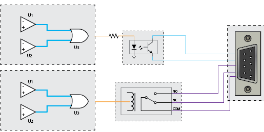
Our product line can offer discrete signals in the form of relays or opto-couplers. These signals are generated internally by the onboard microcontroller but can be shown functionally using the simplified schematic below in Figure 1. Comparators U1 and U2 are used to sense the amplitude of the signal, for instance battery voltage, and determine if it is within or out of a desired range. The outputs of the comparators are input to a decision block, in this case an OR-gate, U3. The gate output can then drive a relay or opto coupler as shown in Figure 2.
The decision block can be an OR gate or any other logic gate or series of gates programmed by the microcontroller. The microcontroller can generate an infinite number of logic combinations to satisfy virtually any requirement.

Relays are chosen when a substantial amount of current and voltage is required to be switched upon some event occurring. Optos are employed when interfacing to other digital circuitry which require a pull-up or pull down function or currents amplitude are less than 10 mA/30V.

RS-232
RS-232 is one of the first popular serial interfaces, originally available on almost all PCs and was commonly used for printers and modems. The RS-232 specification defines signal levels and timing. At a minimum an RS-232 interfaces consists two data transfer signals and a ground. RS-232 uses a point to point connection between two devices referred to as the DCE and DTE. The computer is most often the DTE and the remote device is referred to as the DCE. Data is transferred from a DTE to a DCE over the Transmit data line and data is transferred from the DCE to the DTE over the Receive data line.
In addition to transmit and receive data lines a number of handshaking signal are defined in the RS-232 specification to help regulate date flow. However these are no longer commonly used as processing speeds have increased and with the addition of hardware FIFOs to the interface devices, allowing for reliable data transfers using software only protocols.
Industry standard connectors such as the DB-25 and DB-9 are most commonly used along with pre-defined pin definitions. In some cases non-standard connectors can used such as RJ-45 or others, requiring adapter cables.
RS-232 data transfers are asynchronous, meaning no clock is transmitted. This requires both ends to know the data transfer rate and have a clock accurate to within about 1% to reliably transmit and receive data. Data transfers consists of a stop bit, 5 to 8 bits of data, an optional parity bit and 1 or 2 stop bits. The start bit is used to synchronize the start of data at both ends of the interface. The stop bit is to allow time in-between data words. In general most RS-232 interfaces use 8 data bits to allow transfers of bytes, no parity and 1 stop bit. No parity is often used since the higher level protocol usually consists of a message based check mechanism such as a CRC. Data bits are transferred LSB first. The signal levels for RS-232 are -3V to -15V for a ‘1’(mark) and +3V to +15V for a ‘0’(space). A transfer of one 8bit word is show below:

Advantages:
Driver and application support for all major platforms: Even though RS-232 has been replaced by USB and most new computers do not have an RS-232 port, it generally very easy to add an USB to RS-232 adapter as a virtual com port. Since all major OS’s provide COM port drivers, serial interfaces are still supported and used.
Full-duplex: Messages can be sent and received simultaneously
Disadvantages:
Limited Distance: cable lengths are generally 50 feet or less.
Speed: Speeds above 115,200 bits per second for difficult to implement over any but very short distances. In general speeds of 9600 and 19200 bits per second are more common.
Single-ended: The signals are all referenced to ground which must be common on both ends. Any ground bounce or noise inducing signal/equipment will cause the interface to fail.
Point to point: AN RS-232 interface consist of a computer connected to a remote device. Communication to other device requires multiple RS-232 ports or a remote device that provides relaying of the signal.
RS-485
RS-485 is serial interface using twist pair wires to transfer data. The vast majority of RS-485 implementations use a single pair of wires connected to multiple devices, where at any point of time only one device is the transmitter and the remainder are receivers. The data signal is a differential pair, meaning that one wire of the pair is always in the opposite state of the other. Signal changes are implemented by switching the state, i.e. for a binary '1’ the + signal will be around 2.5V while the - signal will be around 1V, a binary '0' will be the opposite. The RS-485 receiver take the difference of the signal to determine the state. The RS-485 specification defines electrical signal level only, however although most all implementations use RS-232 timing and bit definitions. RS-485 still requires a common ground be used for all devices, however because of the nature of the differential signals and RS-485 receiver, ground bouncing at the end-points is tolerated.

With regard to connectors, there are some de facto standards using a DB-9 connector with designated pin connections for RS-485, however in general there is a wide variety of connector types are used for this interface.
Advantages:
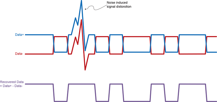
Good noise immunity: since a pair of twist wires is used, any noise pickup is common to both wire and since the RS-485 receiver takes the difference any "common signal" on both pair of wires is neglected. This of course only works up to a point, RS-485 transceivers have a common mode range of -9V to +12V, but for most applications the addition noise immunity is significant. See the example below:

Example of noise immunity of differential signals
Speed and distance: RS-485 can be ran over distance up to 4000m, although the longer the distance the slower the interface speed. For short distance applications the data transfer rate can be much higher than RS-232 or SMBus.
Disadvantages:
Half-Duplex: For the commonly used single pair system, data is transferred in one direction at any point in time.
Bus Configuration: For signal transfer reliability, an RS-485 interface should be used in the multidrop configuration, this is where all connections from the common data line to the device must be short in length. Other topologies such as a star configuration may not have reliable data transfers due to reflections and impedance mismatches, etc, depending on the physical size of the network and data rates.
SMBus is electrically based on the I2C specification with changes and additions for parameters such as timeouts, changes in signal threshold levels, minimum bus speed, etc.
I2C uses a single ended clock and data line shared among all devices on the bus. This protocol allows for master and slave devices, the data (SDA) and clock (SCL) signals are open collector at the devices, pull-up resistors for each signal are placed on the bus. This results in an active ‘0’ state and passive ‘1’ state for both signals. This done to allow for bus arbitration between multiple masters and to allow wait states to asserted by slave devices to slow down the rate of data transfers. All data transfers are performed as 8-bit bytes.
The SMBus master device controls data transfers, multiple masters are allowed. A data transfer consists of a start condition exerted by the master, followed by the 7-bit address of the slave device plus one bit to indicate if the transaction will be a read or write, on the next clock following the address and read/write bit the master looks for an active low acknowledgement bit exerted by the addressed slave. If acknowledged the master continues with reading or writing of data. Each following data byte read or written is acknowledged by the receiving device. The transfer is completed by the master exerting a stop condition. The basic timing is shown below, this is a simple example of a master sending a slave address where there is no acknowledgement, requiring the Master to exert the stop condition to end the transfer.

Advantages:
Based on a standard: The SMBus standard defines the complete message protocol require to communion between devices. RS-232 and RS-485 only define electrical characteristics.
Below is a SMB transaction to read one byte of data based on a SMBus command, S=Start, A=Acknowledge, P=Stop.

A number of SMBus commands are defined, a partial list is shown below:

Disadvantages:
Noise sensitive: I2C was originally designed to connect devices on the same PCB, however has been SMBus is used to connect via a cable to device external to a PCB resulting in noise pickup issues. The protocol allows for CRCs to be added to the message, detected errors than can initiate retransmissions, however not all devices implement this portion of the specification.
Number of device: Although SMBus, like I2C, is multi drop, allowing for multiple device, in general the number of devices is limited by the bus capacitance which increases with cable length. However, in general SMBus is used with a master and only a few devices sharing the bus so this is not normally an issue.
Speed: SMBus is limited to a 100 kHz bus speed but the actual rate of data transfer will be lower due to interface and protocol overhead.
Common serial bus issues:
As discussed, RS-232, RS-485 and SMBus require common ground references, but sometimes references are made to isolated forms of these interfaces, most commonly with RS-485. These isolated interfaces reference electrically isolating the transmitter and receiver at the device from device electronics, however all the interface devices on the communication bus still require a common signal reference among these selves and this may require an additional dedicated power source for the interface.
In large volumes the cost of providing an RS-232, RS-485 or SMBus interface is not significantly different from each other, however in low volumes requirements for custom message protocols for RS-232 or RS-485 may have a slight effect on unit cost.
While many wireless communication options are available, Wi-Fi has become standard for wireless embedded systems. Wi-Fi allows access and control of devices spread over a large area and is well understood in terms of infrastructure and setup.
There are almost unlimited capabilities for adding connectivity over Wi-Fi and while the short-term start-up costs may be high, the long term benefits can lower overall costs. The startup costs would include development of smartphone or laptop applications for connectivity, allowing mobile workers to access applications on the go, increasing efficiency and providing accurate results using fewer personnel.
Advantages:
Scalability: A PC/laptop/smartphone can easily host multiple networks at the same time without additional hardware, the serial interfaces mentioned earlier require dedicated hardware for each network hosted and there are generally limits on the number of interfaces that can be supported.
Infrastructure cost vs. wired networks: Installation of wireless connected devices is up to 10 times cheaper than the wired alterative along with quicker network startup times. There are no costs for the planning required to route wire back to junction boxes or control rooms.
Safer operations: The use of wireless technologies allows complete electrical isolation and physical isolated from hazardous environments.
Data Integrity: Packet protocol acknowledgment is supported by error checking as part of the Wi-Fi protocol. Error checking is designed to ensure that Wi-Fi is not forwarded until it is acknowledged as a correct transmission to guarantee that what is received is identical to what is sent.
Security (over the LAN): Within the local area network, properly configured Wi-Fi provides excellent security using security models like WEP, WPA, WPA2, TPIK and PSK EAP.
Disadvantages:
Privacy and Security (over the WAN/Interface): If access is needed outside a private network then devices must be connected to the internet. Steps must be taken to prevent unwanted parties from controlling the devices or viewing data. This can be in the form of VPNs (additional infrastructure costs) or encryption (additional complexity and device costs).
Cost at the device level: While many PCs have built-in Wi-Fi, adding this capability to network elements is much more costly than the serial interface protocols. Also a network infrastructure is needed and if not already in place this results in additional costs. Depending on the protocol used and the security required, the cost for the devices can escalate further to support additional processing requirements that may be need for encrypted protocols.
Complexity: Due to increases in complexity there are more opportunities of failure. If the infrastructure to support Wi-Fi does not exist in the network it must be added along with trained support personnel.
Compatibility: While control and monitoring functions can be implemented via HTTP or SMTP, this does not fit the need of many users. In these cases custom protocol must be implemented, increasing the startup costs, but lower the longer-term costs as these devices become fully integrated into the existing systems.
PMBus, like SMBus, is based on I2C and has the same characteristics, advantage and disadvantages with respect to the physical interface with some minor differences. PMBus can operate at 400 kHz vs the SMbus 100kHz limit and PMBus allows for transfers of larger blocks of data.
PMBus is an open standard and is optimized for communications and operability between power systems such as power controllers, power supplies, converters, etc. The command structure offers a larger variety of operations than SMBus and include capabilities for controlling and monitoring fans, voltage and current modes, temperature monitoring, load monitoring, voltage control, current control. Etc.
CAN Bus is an open standard allowing node controllers to communicate to each other over a common message based serial bus. It was originally and still primarily used for vehicles but has gradually moved into other applications
CAN is multi-master, each node is required to monitor the serial bus and act on messages of interest. A CAN node can also be a gateway, most commonly this capability is used to connect portions of distant CAN buses over Ethernet.
All nodes on the bus are connected to each other through 120 Ω twisted pair wires. Every node must operate at the same nominal bit rate, up to a maximum of 1 Mbs for short distant networks (<40 meter). Since a separate clock signal is not used, nodes must synchronize to the message being transmitted, this allows for slight variations in oscillator timing between nodes. The CAN specification defines how synchronization is performed as well as definition of the CAN message frame and fields, bus arbitration and error detection. Messages are distinguished by message identifiers. The identifier is unique to the network and defines the content and priority of the message. The content of the message is not defined by the CAN specification but there are a number of industry standard specifications defining the higher level protocols such as node addressing, flow control, transport of large data blocks and application data.
A CAN standard message frame is shown below:

SOF – Start of frame
Arbitration ID – Unique message identifier which also determines the message priority
RTR – Remote Transmission frame – ‘0’ for data frames and ‘1’ for remote request frames, remote request frames are a method for nodes to request data from the source.
IDE - Identifier extension bit, ‘0’ for standard frame as shown about, ‘1’ for extended frame, extended frames have a larger Arbitration ID field size.
r0 - reserved bit, must be ‘0’
DLC – Data length code, number of data bytes, from 0 to 8.
Data – 0 to eight bytes of data
CRC – 15-bit CRC
CRC Del – CRC delimiter, always a ‘1’
ACK – 2 bits, 1st bit is set to ‘0’ by receiver (if any), 2nd bit is ‘1’
EOF – 7 bits, all ‘1’
Advantages:
Robust: The messages contain CRCs and the physical interface is robust allowing for good noise immunity and operation even with failure of one of the twisted pair signals.
Low cost hardware: The only comports need to attach is CAN transceiver and a controller capable of processing CAN data frames.
Built-in Broadcast and message priority: Since all nodes see all messages it is easy to implement broadcast messages that can be sourced by any mode. The bus definition allows prioritization of messages.
Isolation: CAN bus nodes can be isolated, this is relatively straight forward and the CAN bus specifies +5V be provided to the bus side of the interface.
Disadvantages:
Bus efficiency: There is a lot of overhead in the message format considering only a maximum of 8 data bytes can be transferred per frame.
Bus speed: All nodes must operate at the same speed.
Software costs: Adding new custom nodes to an existing bus can involve significant development costs depending on the higher level protocol requirements.
TOOLS
Controls and Monitoring


© 2022 Chargetek, Inc.
1860 Eastman Ave. #107
Ventura, CA 93003
p: (866)482-7930 • f: (805)650-7936
email: sales@chargetek.com
Product Overview


